If passed, something called the Digital Economy Bill over in the U.K. could do the unthinkable in this, the digital age: Ban open wifi spots.
The ban comes as part of a bill that seeks to limit copyright infringement, or something. In summary, schools, small businesses and even libraries would have to effectively become their own ISP and manage the wifi hotspot—or face hefty fines. Even if a shop password-protected their wifi and posted the PW publicly (as they probably should be doing anyway), this "management" would also entail detailed record keeping, as the bill requires that hotspot providers log users who've been on their network. Sounds fun!
I'd love for any UK-based small business owners to weigh in on this debate, and the bill. Is it really as annoying as the ZDNet article makes it sound? Are daily, detailed user records really too much a burden for the corner coffee shop to bear? Light those torches and brandish your pitchforks in the comments! [ZDNET]
The AutoLog WSN Radio modem series has been designed to meet high specifications. It offers very cost effective radio modems for stand alone applications or for integration into OEM products. The design has been optimised for reliability and low current consumption, making the WSN suitable for operation on remote sites without mains power. Applications include security, command & control, data logging, SCADA, telemetry, remote switching or any similar applications where serial data needs to be transmitted and a cable is not the most practical solution. The WSN is available with two different transmit powers. The low power version meets the licence-exempt ETS300-220 specification while the higher power 5W version meets the tougher ETS300-113 and the USA and Canadian specifications.
-120dBm for 12dB SINAD de-emph -117dBm for 12dB SINAD flat
Bandwith
VHF 5MHz without re-alignment UHF 12MHz without re-alignment 870 20MHz without re-alignment
Spurious response
WSN450/869: >65dB WSN170/470/870: >70dB
Blocking
WSN450/869 >85dBuV WSN170/470/870 >90dBuV
Intermodulation
WSN450/869 >60dB WSN170/470/870 >65dB
Adjacent channel
>65dB at 12.5kHz
IF Frequencies
45MHz and 455 kHz
Spurious emissions
WSN450/869 < ETS-300-220 WSN170/470/870 <>
Mute response time
<>
Transmitter:
RF output power
WSN450/869 10mW - 750mW WSN170/470/870 50mW - 5W
Bandwidth:
VHF 10MHz without re-alignment UHF 12MHz without re-alignment 870 30MHz without re-alignment
Internal Modulation:
FFSK, 2 Level FSK, 4 Level FSK & GMSK via the internal modem.
Max. Deviation:
± 7.5kHz max
Adj. Channel Power:
> 65dB at 12.5kHz
Transient response
As per ETS300-113
Spurious Emissions
<>
Rise Time:
<>
Internal Modem:
Radio Baud Rate:
150 – 9600bps over-air
RF Bandwidth:
12.5kHz
Signalling Formats
Programmable for 12.5kHz channel:- Up to 1200bps - FSK with V23 and Bell202 supported. 2400bps - coherent 1200/2400Hz or 1200/1800Hz FFSK. 4800bps - GMSK 9600bps - 4 level FSK.
NRZI:
On or Off
Bit Error Rate:
2400 baud less than 1 in 10^-3 at –120dBm 4800 baud less than 1 in 10^-3 at –117dBm 9600 baud less than 1 in 10^-3 at –115dBm (FEC on) 9600 baud less than 1 in 10^-3 at –112dBm (FEC off)
FEC:
Programmable option at 9600bps
Serial Data:
Serial Interface:
RS232
Format
Asynchronous (or Synchronous with custom software). Programmable; Odd, Even or No Parity, 1/2 stop bits, 7/8 data bits.
Interface Rates:
Programmable 150bps to 38400bps
Serial operation
The WSN requires no knowledge of the data it is transmitting; data can simply be sent and received with minimal delay. Transmission control can either use RTS control signals or be configured for automatic initiation of transmission on receipt of serial data. In either case, the radio provides a CTS output which can optionally be used for flow control. The WSN incorporates an internal buffer to cope with situations where the interface data rate differs from the over-air rate.
Internal soft modem
The WSN features an internal “soft modem” which offers unparalleled performance and flexibility over a wide range of speeds and formats and enables future formats to be handled by software upgrade. Within a 12.5kHz channel, the over-air transmission from the unit can be user programmed for a range of speeds. If the maximum speed is not required, the unit can be configured for a lower speed to give an improved receiver threshold. For 150, 300, 600,1200 & 2400 baud, FSK/FFSK is used with both Bell202 and V.23 supported. At 4800bps GMSK modulation is used, while at 9600bps, the modulation is 4-level FSK.
Channel selection
The WSN can be programmed for simplex or semi-duplex operation with up to 80 discrete channels. Alternatively, complete band allocations like the UK MPT1329 and MPT1411 bands can be loaded. Once programmed, the channels can then be selected via rotary switches on the front panel.
RF power
The transmit power can be accurately set using a locally connected PC with the supplied software. There are two transmit power ranges available. The low power WSN450 & WSN869 can be set between 10mW and 750mW, while the higher power WSN170, WSN470 & WSN870 versions can be set between 50mW and 5W.
Programmability
The parameters of the WSN can be configured through the local serial port using DOS or Windows 95/98/2000/XP based software. The individual configurations can be stored on disc for future use or printed.
Status LEDs
The WSN has 5 LEDs to enable the operator to see at a glance the status of the radio and its interfaces. The System LED provides the operator with a quick visual health check and if the software detects an error, a code is flashed on the LED to indicate the error.
Squelch tail elimination
For old or non tolerant protocols, where the presence of a mute (squelch) tail may cause a problem at the end of a message, a simple packetisation option can be enabled using the configuration software
Forward error correction
Forward error correction is a programmable option at 9600bps, but as with all FECs, the associated overhead will reduce the effective data throughput rate when it is selected. Error correction offers insignificant performance improvements below 9600bps so the option is permanently disabled at those lower rates.
"RSSI" Receive signal strenght indication
The RSSI signal is accurately measured by an internal A-D converter and compared to an individually calibrated RSSI graph within the processor. The signal strength can then be accurately read in engineering units from a PC connected to the serial port.
Power save mode
The WSN has both internal and external power save modes.
Internal Power Save Mode The microprocessor controls the on/off function of the receiver and after a pre-programmed time the MPU will switch on the receiver to look for a carrier. If a carrier is not detected then the transceiver goes back into sleep mode. If during the time the transceiver is awake a carrier is received, the unit will stay awake. After the carrier drops out, the receiver will stay awake until the programmed resume time elapses. Once the resume time has elapsed the transceiver will go back into sleep mode. The power-save, wake and resume times are all user programmable.
External Power Save Mode In the external mode the ON/OFF function of the modem is controlled by the host via the DTR line. Tx timeout-timer
The transmitter within the WSN has a time-out timer which allows the maximum continuous transmission time to be set in order to prevent channel blocking due to a to fault. The timer operates in all modes and can be programmed in one second steps between 0 and 255 seconds. If programmed and the time is exceeded, transmission will cease until the action that normally causes transmission is removed and then re-applied.
PC software
Dedicated PC software running under DOS or Windows 95/98/2000/XP allows configuration of the radios. This software provides unrivalled versatility combined with ease of use for the operator.
The XStream-PKG-T Telephone RF Modem provides long range wireless links between a fully-functional on-board telephone module and remote radio modems (XTend OEM RF modules embedded into other devices, RS-232 / RS-422 / RS-485 RF modems, etc.).
With a built-in speaker, RSSI (Received Signal Strength Indicator) LEDs and outstanding range capabilities, the XTend-PKG-T is an excellent solution for creating reliable wireless links and extending range between remote devices and public telephone lines.
Product summary: ISM 900 MHz or 2.4 GHz operating frequencies 100 mW (900 MHz) or 50 mW (2.4 GHz) power output (up to 20 mile range) RS-232/485 interfacing built-in Commercial (0 to 70° C) or Industrial (-40 to 85° C) temperature ratings FCC/IC/ETSI/CE approved (Click here for comprehensive list of agency certifications) Advanced networking & low-power modes supported All MaxStream radio modems are manufactured under ISO 9001:2000 registered standards and backed by MaxStream’s one-year warranty.
Additional Features
For volume pricing please call our sales team on 0044 (0) 1273 248977. Or Click Here to request a quote.
I began to recognize the Ubuntu LTS from 6:06-Drapper Drake, Edgy Eft 6:10, starting with (dual boot) since 7:04 and Feisty Fawn 7.10 Gutsy Gibbon, but only actually use to work since the 8.04-LTS Hardy Heron, Intrepid Ibex 8:10, and 9:04 Jaunty Jackalope (although I still like Mandriva). Only in the final releases, I would not miss the upgrade (thanks to the motivation of this accident and real assistance Riyogarta mas). Likewise, many who I did not know. Not for nothing, maybe just because my brain is too slow to follow the progress of thinking too fast. Plus, it was too long window poisoning.
When I use Hardy Heron, I started using bluetooth modem for hape reliable Internet connection (dialup). Play KPPP, Gnome PPP and wvdial getting used to. When changing Intrepid Ibex, I initially bluetooth trouble connecting via dialup modem, although soon be overcome thanks to the help Kurnia, bloggers who are also members of the River Solo KPLI. Not long to feel comfortable, come again Jaunty Jackalope. First I was confused, why is not there wvdialnya, but lived for another internet connection, enter the terminal, type sudo apt-get install wvdial, right deh! ...
Well ... recently I got a loan hape Sony Ericsson K510i. Rather lawas hell! can only gprs, not 3G. But can be used as a modem either via Bluetooth or USB cable through luggage. On Windows, connect it via cable to function after the driver install CD is in her luggage as well.
Fad, I'm content with Flash cards, then on again and the data cable from the SE K510i I tried to plug in the USB port on my laptop which already had Jaunty Jackalope. Tuiiiinggggg ...
already been detected? There are two options that appear on the screen SE K510i, the first to transfer files, and the second phone mode. I select the phone mode. Immediately on the laptop screen appears saying Welcome ...
I try to click the network connection icon in the top panel, was actually detected and need configuration.
When I click "configure" option appears the state and providers are used. Of course I choose Indonesia, and because the cards used in the SE K510i is subscribed Flash Card Hello, I select Telkomsel as providernya.
At this point actually being able to directly connect, but I try to peek settings to click with the right network connection icon in the top panel, click again to edit connection.
There are several options there, Wired, Wireless, Mobile Broadband, VPN, and DSL. Telkomsel setting in Mobile Broadband. I just adjust the username and password, all my kosongi according to the instructions I get the first time I subscribed Flash. Dialing can numbernya * 99 #, can also * 99 *** 1 #, it could APN internet, can also telkomsel.
And, I try to connect to the Internet with network connection click the icon - I click on Telkomsel. I do not know why there are two types of modems on the SE K510i. Later, when I check in Windows, it also had two. I use one that just might ...
Ops ... clicked out there was another warning, yes of course I invite only (yahoo)
It's connect! Network connection icon is now changed to an antenna tower image. Telkomsel Connection Established ...
Yeach ... I apologize if I made too much detail. I am sure, many of sedulur sekaliyan far more understanding. However, this is what I experienced. Apparently a lot of things so easy in Linux.
Because so easy and I did not realize it (I usually take the more difficult path, with a wvdial in the terminal), I reverse-engineer the way internet connection (dialup) in the previous Ubuntu release. I use the Live CD / Installer Ubuntu for 8:04, 8:10, and 9:04.
This is my observation: (funkydance)
Ubuntu Linux 8.04-LTS Hardy Heron: wvdial available, mobile broadband connection is not available.
Ubuntu Linux 8.10 Intrepid Ibex: wvdial and mobile broadband connection available.
Ubuntu Linux 9:04 Jaunty Jackalope: wvdial is not available, mobile broadband connection available.
As if the Blackberry didn't have enough uses already, it can be used as a modem too. Read this to find out more about how to use your Blackberry as a modem.
Most of the time when you are traveling, you have access to free wi-fi connections in your hotel room, and even in the local McDonald's. In the event that you find yourself stuck, needing to use your laptop with no wi-fi connection in site, all you need to do is use your Blackberry as a modem. You will need to make sure that your Blackberry is one of the models with the “tethered modem capability.” These phones are:
BlackBerry® 7130c
BlackBerry® 7130e
BlackBerry® 7250
BlackBerry® Curve 8300
BlackBerry® Curve 8310
BlackBerry® Curve 8320
BlackBerry® 8703e
BlackBerry® 8705g
BlackBerry® 8707g
BlackBerry® 8800
BlackBerry® 8820
BlackBerry® 8830 World Edition
If you are using one of those Blackberry phones, follow these instructions to tether your phone to your laptop to use it as a modem.
Make sure you have a USB cable, and the BlackBerry Handheld Manager installed on your laptop. Blackberry Handheld Manager is part of the Desktop Manager software that is required in order to install applications to your device. If you do not have it, you can download it to your laptop from Blackberry. (If you do not have this before needing your phone as a modem, you will have to find a source of wi-fi before you can do it.) All you need to do is open the Desktop Software and the Handheld Manager will also run.
You'll need to make sure you have the necessary modem drivers on your phone before using it as a modem. Most of the models above come with the drivers already loaded on them. If not, you'll be able to get the necessary drivers from the Blackberry Desktop Manager software.
Once you have determined that you have everything you need in order to use your Blackberry as a modem, you'll need to go into your phone and configure the settings specific to your provider and ensure that your modem drivers are working correctly. Another how to for this will be coming along soon.
Setup a new connection in your laptop. The setup for this follows the setup process for any other Internet connection and will vary depending on which version of Windows you are using.
Now, disable IP Header Compression with the following steps:
Start Menu->Network Connections->”BlackBerry Modem” (or whatever you chose to name the connection you set up in the previous step.
Click Properties Button
Click Networking Tab
Select “Internet Protocol (TCP/IP)”
Click Properties.
Click Advanced.
Disable “Use IP header compression” with the checkbox.
Close out all the menus by clicking OK.
Connect the phone to the laptop with USB, open the Blackberry Desktop Management Software, click the Modem icon and find the available connections. You will be able to use the Internet on your laptop with the Blackberry serving as your modem.
Serial communications with RS232. One of the oldest and most widely spread communication methods in computer world. The way this type of communication can be performed is pretty well defined in standards. I.e. with one exception. The standards show the use of DTE/DCE communication, the way a computer should communicate with a peripheral device like a modem. For your information, DTE means data terminal equipment (computers etc.) where DCE is the abbreviation of data communication equipment (modems). One of the main uses of serial communication today where no modem is involved—a serial null modem configuration with DTE/DTE communication—is not so well defined, especially when it comes to flow control. The terminology null modem for the situation where two computers communicate directly is so often used nowadays, that most people don't realize anymore the origin of the phrase and that a null modem connection is an exception, not the rule.
In history, practical solutions were developed to let two computers talk with each other using a null modem serial communication line. In most situations, the original modem signal lines are reused to perform some sort of handshaking. Handshaking can increase the maximum allowed communication speed because it gives the computers the ability to control the flow of information. High amounts of incomming data is allowed if the computer is capable to handle it, but not if it is busy performing other tasks. If no flow control is implemented in the null modem connection, communication is only possible at speeds at which it is sure the receiving side can handle the amount information even under worst case conditions.
Original use of RS232
When we look at the connector pinout of the RS232 port, we see two pins which are certainly used for flow control. These two pins are RTS, request to send and CTS, clear to send. With DTE/DCE communication (i.e. a computer communicating with a modem device) RTS is an output on the DTE and input on the DCE. CTS is the answering signal comming from the DCE.
Before sending a character, the DTE asks permission by setting its RTS output. No information will be sent until the DCE grants permission by using the CTS line. If the DCE cannot handle new requests, the CTS signal will go low. A simple but useful mechanism allowing flow control in one direction. The assumption is, that the DTE can always handle incomming information faster than the DCE can send it. In the past, this was true. Modem speeds of 300 baud were common and 1200 baud was seen as a high speed connection.
For further control of the information flow, both devices have the ability to signal their status to the other side. For this purpose, the DTR data terminal ready and DSR data set ready signals are present. The DTE uses the DTR signal to signal that it is ready to accept information, whereas the DCE uses the DSR signal for the same purpose. Using these signals involves not a small protocol of requesting and answering as with the RTS/CTS handshaking. These signals are in one direction only.
The last flow control signal present in DTE/DCE communication is the CD carrier detect. It is not used directly for flow control, but mainly an indication of the ability of the modem device to communicate with its counter part. This signal indicates the existence of a communication link between two modem devices.
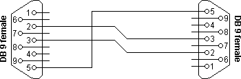
Null modem without handshaking
How to use the handshaking lines in a null modem configuration? The simplest way is to don't use them at all. In that situation, only the data lines and signal ground are cross connected in the null modem communication cable. All other pins have no connection. An example of such a null modem cable without handshaking can be seen in the figure below.
Simple null modem without handshaking
Connector 1
Connector 2
Function
2
3
Rx
Tx
3
2
Tx
Rx
5
5
Signal ground
Compatibility issues
If you read about null modems, this three wire null modem cable is often talked about. Yes, it is simple but can we use it in all circumstances? There is a problem, if either of the two devices checks the DSR or CD inputs. These signals normaly define the ability of the other side to communicate. As they are not connected, their signal level will never go high. This might cause a problem.
The same holds for the RTS/CTS handshaking sequence. If the software on both sides is well structured, the RTS output is set high and then a waiting cycle is started until a ready signal is received on the CTS line. This causes the software to hang because no physical connection is present to either CTS line to make this possible. The only type of communication which is allowed on such a null modem line is data-only traffic on the cross connected Rx/Tx lines.
This does however not mean, that this null modem cable is useless. Communication links like present in the Norton Commander program can use this null modem cable. This null modem cable can also be used when communicating with devices which do not have modem control signals like electronic measuring equipment etc.
As you can imagine, with this simple null modem cable no hardware flow control can be implemented. The only way to perform flow control is with software flow control using the XOFF and XON characters.
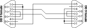
Null modem with loop back handshaking
The simple null modem cable without handshaking shows incompatibilities with common software. The main problem with this cable is that there is a possibility for the software to hang if it checks the modem signal lines in a proper way. I.e. with this null modem cable, good written programs will perform worse than badly written programs.
To overcome this problem and still be able to use a cheap null modem communication cable with only three lines in it, a fake null modem cable layout has been defined. The null modem cable with loop back handshaking resulted from this.
Null modem with loop back handshaking
Connector 1
Connector 2
Function
2
3
Rx
Tx
3
2
Tx
Rx
5
5
Signal ground
1 + 4 + 6
-
DTR
CD + DSR
-
1 + 4 + 6
DTR
CD + DSR
7 + 8
-
RTS
CTS
-
7 + 8
RTS
CTS
The main purpose of this null modem cable is to let well defined software think there is handshaking available, with a null modem cable which has no provisions for it.
Compatibility issues
Consider first the DSR signal (pin 6). This input indicates that the other side is ready to start communicating. In the layout, the line is linked back to the DTR output (pin 4). This means, that the software doesn't see the ready signal of the other device, but its own. The same holds for the CD input (pin 1). The assumption is, that if software has been written to check the DSR line to test communication availability, it will probably also set the DTR output to indicate its own state. This is true for at least 99% of all serial communication software. This implies that at least 99% of all serial communication software is capable of faking its own DSR check with this null modem cable.
The same trick is used with the CTS input. In the original use, RTS is set, and then CTS is checked before starting the communication. By setting the RTS output (pin 7) the CTS input on the same connector (pin 8) is receiving clearance immediately. There is no possibility of a software hangup because of dangling RTS requests.
Other issues to consider
The null modem cable with loop back handshaking is often advised as the best low cost available null modem cable. But, is it really so good? The simple null modem cable without handshaking has the disadvantage that it does not permit proper written software to communicate with it. Software which is aware of the lack of handshaking signals can however use it without problems.
The null modem cable with loop back handshaking can be used with more software, but it has no functional enhancements over the simple cable! There is no way both devices can control data flow, other than by using XON/XOFF handshaking. If the software is designed for using hardware flow control it seems to work with this null modem cable, but on unpredictable moments, data loss may occur. This means that the null modem cable allows communication as long as no flow control is needed, but when data speeds reach the limit the receivers can handle, communication may stop immediately without an assignable reason. Therefore, although this null modem cable is cheap and easy to make, use it with care! Despite these warnings, this type of null modem cable has been used successfully between Windows 95/98/ME computers with a Direct Cable Connection.
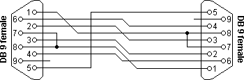
Null modem with partial handshaking
The simple null modem cable and the null modem cable with loop back handshaking are useful, but have no provisions for hardware flow control. If it is absolutely necessary that hardware flow control is used, the null modem with partial handshaking can be an alternative.
Null modem with partial handshaking
Connector 1
Connector 2
Function
1
7 + 8
RTS2
CTS2 + CD1
2
3
Rx
Tx
3
2
Tx
Rx
4
6
DTR
DSR
5
5
Signal ground
6
4
DSR
DTR
7 + 8
1
RTS1
CTS1 + CD2
Compatibility issues
This null modem cable is the best of two worlds. There is the possibility of hardware flow control without being incompatible with the original way flow control was used with DTE/DCE communication. Let us first consider the RTS/CTS flow control lines present on pins 7 and 8. As with the loop back null modem cable, these signals are not connected to the other device, but directly looped back on the same connector. This means, that RTS/CTS flow control is allowed to be used in the software, but it has no functional meaning. Only when the software at the other side checks the CD signal at pin 1, the RTS information will reach the other device. This would however be only the case in specifically developed software which uses the CD input for this purpose.
More important however is the cross connection of the DSR (pin 6) and DTR (pin 4) lines. By cross connecting these lines, their original function is simulated pretty well. The DTR output is used to signal the other device that communication is possible. This information is read on the DSR input, the same input used for this purpose with modem communication. Because of this cross connection, the DTR output line can be used for simple flow control. Incomming data is allowed when the output is set, and blocked if the output is not set.
Software using only the RTS/CTS protocol for flow control cannot take advantage of the partial handshaking null modem cable. Most software however will also check the DSR line and in that case—when using the null modem cable with partial handshaking—the best possible hardware flow control can be achieved which is still compatible with the original use with modems.
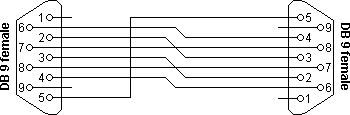
Null modem with full handshaking
The most expensive null modem cable is the null modem cable suitable for full handshaking. In this null modem cable, seven wires are present. Only the ring indicator RI and carrier detect CD signal are not linked. The cable is shown in the following figure.
Null modem with full handshaking
Connector 1
Connector 2
Function
2
3
Rx
Tx
3
2
Tx
Rx
4
6
DTR
DSR
5
5
Signal ground
6
4
DSR
DTR
7
8
RTS
CTS
8
7
CTS
RTS
Compatibility issues
The null modem cable with full handshaking does not permit the older way of flow control to take place. The main incompatibility is the cross connection of the RTS and CTS pins. Originally, these pins are used for a question/answer type of flow control. When the full handshaking null modem cable is used, there is no request anymore. The lines are purely used for telling the other side if communication is possible.
The main advantage of this cable is, that there are two signalling lines in each direction. Both the RTS and DTR outputs can be used to send flow control information to the other device. This makes it possible to achieve very high communication speeds with this type of null modem cable, provided that the software has been designed for it. Because of the high possible connection speed, this null modem cable can be used with Interlink to connect two MS-DOS PC's.
This is the type of cable Microsoft recommends for the direct cable connection in their knowledge base article. For the DB9 connector they also added a connection of DTR to CD on each connector but they didn't define this connection for the DB25 connector version and they also didn't mention the CD input in the descriptive text, so it is safe to leave the CD input disconnected.
Null modem layout selection table
The right null modem cable to choose mainly depends on the application and the software that will be used. As a general guide line, I would advise the following.
Choose your null modem cable
Cable without handshaking
Loop back handshaking
Partial handshaking
Full handshaking
Software flow control only
+++
++
+
+
DTE/DCE compatible hardware flow control at low speeds
-
+++
++
-
DTE/DCE compatible hardware flow control at high speeds
-
+
+++
-
High speed communication using special software
-
-
++
+++
+++ ++ + -
Recommended cable Good alternative Works, but not recommended Does not work
The null modem cable with partial handshaking works in most cases. If you are developing software which must work with all kinds of cables, it is best to use software flow control only and ignore all modem control inputs.
Did you ever imagine that your blackberry can be used as a modem too. Yes, thanks to berry4all, a free, open-source software for using your Blackberry on alternative OS’es (Linux, OSX)It has been tested on Linux (Debian, Ubuntu, Mint, Fedora) and OS X (Tiger (PPC & x86), Leopard) and is found to be good. Let's see and learn how to use your blackberry as a modem in Linux and OSX.
Linux
This script requires python, pppd, libusb and the python usb(pyusb) module installed:
Modem signal is weak, of course, hinders our activities as a netter for slow Internet connection. Moreover, if the distance of our house with the BTS transmitter far enough away so consequently the captured signals at one or two bars, very annoying is not it? The period we have to bring a laptop and a modem to the transmitter tower and ngenet there? It is impossible! Well, because I also experienced similar problems I was a little-obok content mengobok Google and thankfully I got some references to improve the modem signal, which is ... Kilik Wok Antenna inspired from Wok Antenna Bolic! The antenna is made of this kitchen tool can improve signal reception, the modem up to twice as long!
Wok Kilik antenna is actually just a regular frying pan or pot on the call that is used as a container in the kitchen cooking. How it works simple, pan serves as a modem or a booster amplifier in the receive signal, well because its so merupai this dish can be called Wok Bolic (Bolic = dish / parabolic) simple, hehehe ..
How to manufacture and use Kilik Wok / Wok Bolic Cafeblogger version. The materials need to be prepared include:
First coated aluminum foil on the surface of the pan, then aluminum foil insulation is in order. Put the modem / phone you who want to use as a modem in the middle of the pan, then find the right position until you mendaptkan strong signal. For example please look at my own Kilik Wok:
Kilik Wok this antenna can be placed anywhere in accordance with the needs and conditions of your room, find the most suitable position for the strongest signal, this Kilik pan can be placed outside the room like a regular dish for better signal maximum captured.
Your friends might see Kilik's Wok blogikrar as comparative material, Wok Kilik blogikrar not wearing aluminum foil, and I use aluminum foil because when trying to pan for the first Kilik does not seem to change my hape modem signals, well after I added a layer aluminum foil, then the modem signals D1200P Mobile Smart is increased! As a result of normal Internet speed lemot became fast enough, can be seen in Screenshoot download the following:
Well if there are things that are still not clear, or want to ask please comment, please feel free to ya ..
Simply put there are some tricks that might be very helpful process ADSL installation & operation.
* On the phone cable to be connected to an ADSL modem, make sure the splitter has been installed. * Put the phone in the phone cable to ADSL, listen - if there is a dial tone? If there is no dial tone is a cable problem. Make sure also that the tone of the hearing quite clearly, is the connection good enough. * Remove the phone, connect the ADSL modem to the telephone cable. Connect the LAN cable to the computer. Input power supply to the PLN ADSL modem. * Set the IP address for a family computer with ADSL modem, usually a family 192.168.1.x or 10.0.0.x. * Ping ADSL modem from computer. Some of the default IP address ADSL modem is 192.168.1.1, 192.168.2.1, 10.0.0.2. * If you have an ADSL modem installation CD, run the CD & configuration using the CD will be much easier than through the Web. * Check the status of an ADSL modem - if connected properly or not.
Which will make it a habit is called when the check status of an ADSL connection, the problem we need to check the status page which is generally an ADSL modem configuration can provide much useful information for troubleshooting. Really simple logic problems
* There is no dial tone - that the phone cable problem. * On the status page, ADSL does not work synchronization to Telkom, there are several possibilities o poorly telephone cable, can be checked by placing the receiver and listened for the sound connection "krosok-krosok". o ADSL modem that is used is not good, my experience shows in many ways an ADSL modem that is used can not stand the condition of the telephone network in Indonesia. o Telkom DSLAM at the central is not good, it rarely happens. * On the status page, ADSL was unable to obtain IP address, there are several potential problems, o The connection between the DSLAM in Telkom to the troubled ISP. o Server on ISPs that are problematic. * On the status page, ADSL does not work login / authentication to the ISP, then username / password that you use one.
By knowing the status of the condition, we can complain / problem to determine the right place. Not all problems come from Telkom. My experience has been that often the problem actually comes from an ADSL modem is not good.
Many types of ADSL modem like the kind of speed, combined type router into the modem, integrated wireless, USB and Ethernet are united by a modem and so on.
ADSL modem has been developed by the placement of additional devices. You can use an ADSL modem to 1 computer and 4 are connected by an ethernet LAN. Or you can use an ADSL modem with ethernet and USB output only when only requires 2 connections to the PC.
So many modem provided would facilitate the user. But if you only need a simple modem connection can select the type of modem with an ethernet connection and USB ports are determined enough. Certainly more and more needs and wants you to use the type of device to an ADSL modem, the more expensive price of the modem.
But some features that need attention. Because Indonesia is slightly different in the way of calculation than other countries that have more established organized internet connection with an ADSL modem. There is good use of modems with the automatic connection feature on and off. ADSL modem with these features will save the cost of your connections, especially in Indonesia is still in use calculation of the amount of time or the bandwidth used. If you use the service without limit, the type of ADSL modem on and off is not really necessary.
Image below is the most expensive modem offered by Telkom Rp.350.000 price or slightly more expensive than the USB modem dial-up. The price is very reasonable if you want a simple ADSL modem. Only available USB port and Ethernet. If you need additional computer connections to more than two pieces, then the solution to this cheap modem can be added with an ethernet hub to share the connection to other PCs.
A little advice for choosing the DSL modem, you should ask also to other colleagues who are using ADSL connection. We got a lot of different information on the quality of the modem, and DSL modem capability is only distinguished from the additional features owned. Most important is the resilience of the DSL modem. If you use the connection without limits, endurance modem becomes the most important part. Your DSL modem at least not too often hangs due to work too long or become hot.
More and more features in the modem will make the modem gets hot because of the additional chip board inside the modem, but meets the integrity of the connection types such as WiFi, Ethernet and USB hub. Using a DSL modem with a simple feature will limit the ability of the DSL modem itself, especially if you want to add connections to another computer. So adjust the needs and desires that you need.
did you know that the speed Internet connection can be improved by changing some specific settings in Windows. Although it was a lot software to speed up your internet connection may also not be a loss to know how to speed up the modem in "manual" as listed below:
First way
1. From the Control Panel, click the Modems icon.
2. In the Modem Properties dialog box, select the modem that will be changed settingnya and click on the Properties button
3. On the General tab, change the Maximum Speed to 115,200
4. Move to the Connection tab and click the Port Settings button.
5. From the dialog box Advanced Port Settings, put a check on the Use FIFO buffers. Then change the Receive Buffer and Transmit Buffer 14 a 16. Then click OK.
6. Click the Advanced button, check mark the Use Flow Control.
7. Then select the radio button Hardware. In the Extra Settings, fill with C1D2E1Q0V1X4% C0 S7 = 55 S11 = 55 S0 = 0.
Both ways
1. From the Control Panel, click the System icon.
2. Move to the Device Manager tab.
3. On the Ports (COM & LPT), select the port used by your modem and click the Properties button.
4. Moving to Port Settings tab.
5. In the Bits per second, with 921,600 contents.
Third way
1. Open the System.ini file located in C: Windows.
2. In the [386Enh], add the COM1Buffer = 16,384. Change COM1 with port used by the modem.
The U.S. Robotics 56K Fax Modem is designed to be easy to install and use, yet loaded with the features demanded most. It includes the latest V.92 technology for faster uploads (great for on-line gaming, posting digital photos, sending e-mail with large attachments, etc.), faster connections and a host of enhanced telephony capabilities.
Host Interface
Serial
Interfaces/Ports
1 x RS-232 Serial
Product Type
Data/Fax Modem
Manufacturer Part Number
USR015631A
Manufacturer Website Address
http://www.usr.com
Manufacturer
U.S. Robotics.
Product Model
5631
Product Name
56K Fax Modem
Modem/Fax Data Rate
56 Kbps Data
Package Contents
56K Fax Modem
Power supply
Phone cord and/or adapter/splitter
Serial cable
Installation Guide
Installation CD-ROM
User's guide
Data/fax software Instant Update, Internet Call Notification, and value-added software collection
Form Factor
External
Standard Warranty
2 Year Limited
Host Interface
Serial
Interfaces/Ports
1 x RS-232 Serial
Bus Type
Serial
Product Type
Data/Fax Modem
Manufacturer Part Number
USR015631A
Manufacturer Website Address
http://www.usr.com
Manufacturer
U.S. Robotics.
Product Model
5631
Product Name
56K Fax Modem
Brand Name
U.S. Robotics
Modem Speed
56
Modem/Fax Data Rate
56 Kbps Data
Package Contents
56K Fax Modem
Power supply
Phone cord and/or adapter/splitter
Serial cable
Installation Guide
Installation CD-ROM
User's guide
Data/fax software Instant Update, Internet Call Notification, and value-added software collection